Calculating fault thickness
With the Fault Thickness form (model > Fault Seal > Fault Seal Modeling > Fault Thickness) you calculate the thickness of fault rock which is input to the fault transmissibility calculation (see Calculating fault transmissibility). The calculation is done for each 'calculation point' (i.e. the centerpoint of the common area of any two cells which are in touch across a fault) according to the following formula:

In natural fault systems, the thickness of the fault rock in the central slip plane of the fault and its surrounding damage zone both generally increase linearly with displacement. It is important to note that most geological datasets of fault displacement-thickness ratio show a lot of scatter, because there is a lot of natural variability in fault zones. We can, however, approximate the general relationships between displacement and thickness in the model.
Fault displacement is determined from the model grid by the geometric property (as calculated with the Geometric Properties tool) that you select on the form. The 'displacement to fault thickness' ratio is a value which you enter on the form. You can derive this value from the positive linear correlation which exists between fault displacement and fault thickness as demonstrated in the below image. The default ratio is 100, which means 100 meter displacement equals 1 meter of fault thickness. You can change the ratio according to specific circumstances. But it is important to note that in natural faults, the general rate of fault thickness increase drops off exponentially once the fault reaches 100-150m of displacement (e.g. Solum & Huisman 2017). Host lithology can have a second-order influence on fault thickness especially in small scale displacement if the fault displacement is contained within e.g. a sand-dominated sequence versus a fault displacement contained within a shale dominated sequence. At larger displacement, however, faults tend to pass through a mix of lithologies, so that the fault rock and damage zone thickness is influenced by that mix. In that situation, the fault damage zone is offset by the fault, and often thicker on one side than the other according to the influence of the sand- or shale-dominated sequences that are slipped and juxtaposed on either side of the fault.
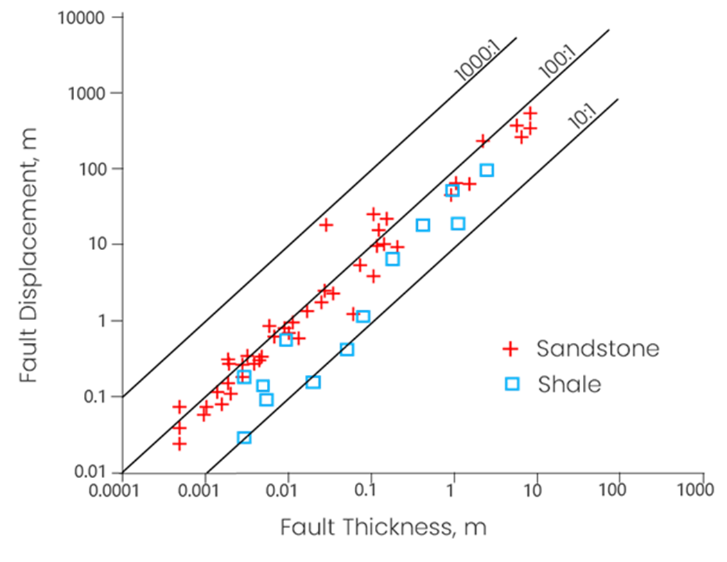
Fault Displacement - Fault Thickness ratio for sandstone and shale shows a linear relation on a logarithmic scale. Modified from Christopher H. Scholz The Mechanics of Earthquakes and Faulting, published by Cambridge University Press. click to enlarge
Solum, J.D. & Huisman, B.A.H. (2017) Toward the creation of models to predict static and dynamic fault-seal potential in carbonates. Petroleum Geoscience, 23, 70-91.
Weighing by lithology (optional)
As the above plot shows, shale has a lower 'fault displacement - fault thickness' ratio than sandstone. This means that with equal fault displacement, faults in shale are thicker than in sandstone. For this reason a 'tuning' option (optional) is provided on the Fault Thickness form in the form of weight factors for sandstone and shale. When using this option, you can make additional fault thickness variations along the fault according to the lithology encountered, in addition to the thickness variation calculated from the fault displacement.
When applying weight factors, at each 'calculation point' it is determined whether the connecting grid cells (i.e. the two grid cells that make up the calculation point) are sand or shale. This is done based on the Vshale cutoff value that you enter on the form. The corresponding weight factor is then applied to the ratio-based fault thickness to come to the final fault thickness at the point of calculation.
The calculations are as follows:
Sand-Sand connection:

Shale-Shale connection:

Sand-Shale connection:

When applying weight factors, be aware of the following:
- Lithological control on variation in fault thickness is most obvious in small (cm-m) displacement scales, and less obvious as the faults become bigger.
- Fault thickness increase essentially stops once the fault gets to 100-150 m displacement, so there is a natural limit to fault thickness (e.g. at 100:1 ratio, thickness maximum 1-1.5 m, see 'Use maximum thickness' below).
- With a weight factor of 1 as reference, a weight factor of 1.2 (for example) will add an extra fault thickness of 20% to the ratio-based fault thickness. Be careful to avoid modeling non-possible fault thicknesses, see 'Thickness Weight Factor' below.
To calculate fault thickness
- At the top of the form, in the Model drop-down list, select the relevant Fault Seal Model.
- Fault offset Select the geometric property that determines the fault displacement in the fault thickness calculation. You need to have calculated the property with the Geometric Properties tool (see Requirements and input). If you do not have the selected geometric property, you will get an error when clicking Apply or OK a the base of the form.
- Displacement to thickness ratio Enter the displacement to thickness ratio. See the paragraph and image at the top for background information. The default value is 100 (i.e. a fault displacement of 100 m. results in a fault thickness of 1 m.). In most cases the ratio stays within the range of 25 to 150.
- Use maximum thickness Fault thickness greater than this value will be set to this value. It is recommended to use this option, as fault thickness does not linearly increase with increasing fault offset; beyond a certain offset, fault thickness will no longer increase. It is recommended to use the default value around 1 metre.
- Weigh by lithology (Optional) You can tune the calculated fault thickness by using a weight factor for sand or shale, see above. To do this, check the box and proceed with the steps described below.
- Vshale property Select the Vshale property on the basis of which lithology (sand or shale) for weighing is determined. Note that the property you select here is only used for weighing by lithology and not in any other way in the workflow.
- Vshale cutoff Enter the Vshale cutoff value on the basis of which lithology (sand or shale) for weighing is determined. By default, the Vshale cutoff value as set on the Fault Clay Content form > settings for SSF are used. Note that the value you enter here is only used for weighing by lithology and not in any other way in the workflow.
- Thickness Weight Factor Enter the weight factor(s) for sand and/or shale. Weight factor 1 will give no growth/shrinkage of the ratio-based fault thickness. A weight factor of 1.2 for shale, for example, will add an extra 20% thickness to the ratio-based fault thickness at each shale-shale cell connection across the fault. A weight factor of 0.9 for sand will reduce the ratio-based fault thickness with 10% at each sand-sand cell connection across the fault. In case of a shale-sand connection, the average weight factor is taken, see above. It is recommended to use this option with constraint and to stay within the range of 0.5 to 1.5.
- At the base of the from, click Apply to keep the form open or Next to move to the next step of the workflow, Calculating fault transmissibility. Upon clicking, property 'Fault thickness' is calculated and added to the respective point set(s) in the 'Fault Seal' surface set in the JewelExplorer. You can visualize the property in the 3D View.